Sapphire's Ancient History, Part 3: the stuff in the middle

I the previous two posts, part one and part two, I went over the stuff you can see (the buttons and everything external) and the stuff you can’t see (the electronics). This post is something that would be easy to overlook, but turns out to be the most important. Really.

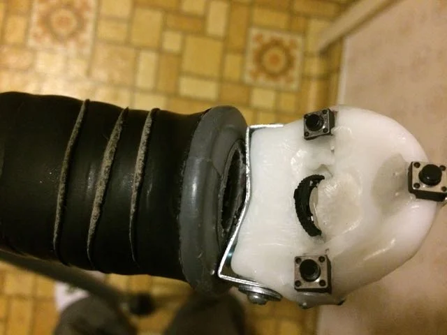
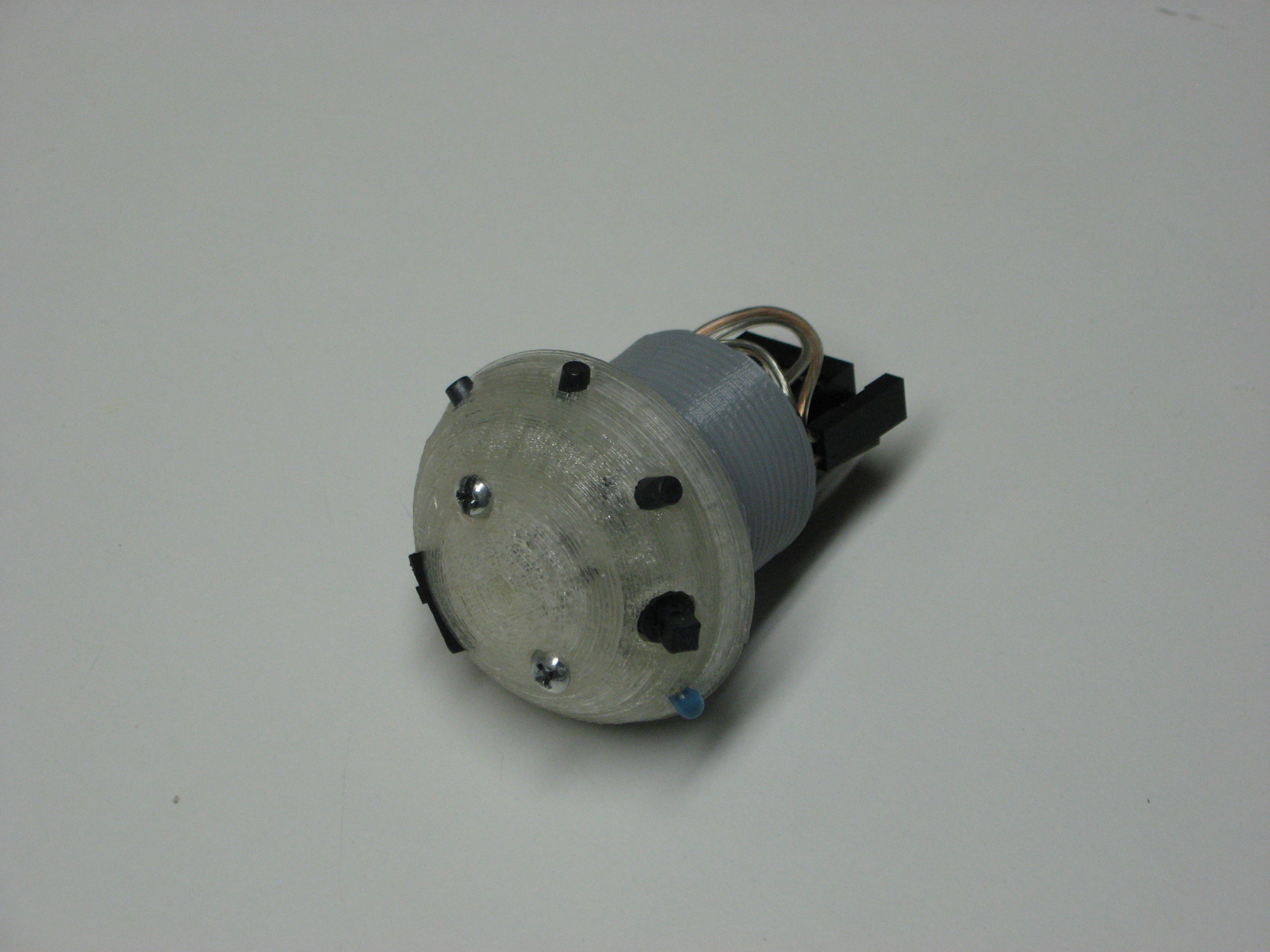
The “stuff in the middle” is the hardware that is used to connect the electronics to the external controls. You can see it in the photo to the right, it is the gray part between the clear/white part and the wire connector. It needs let the controls be adjustable and protects the wiring while still holding everything in place.

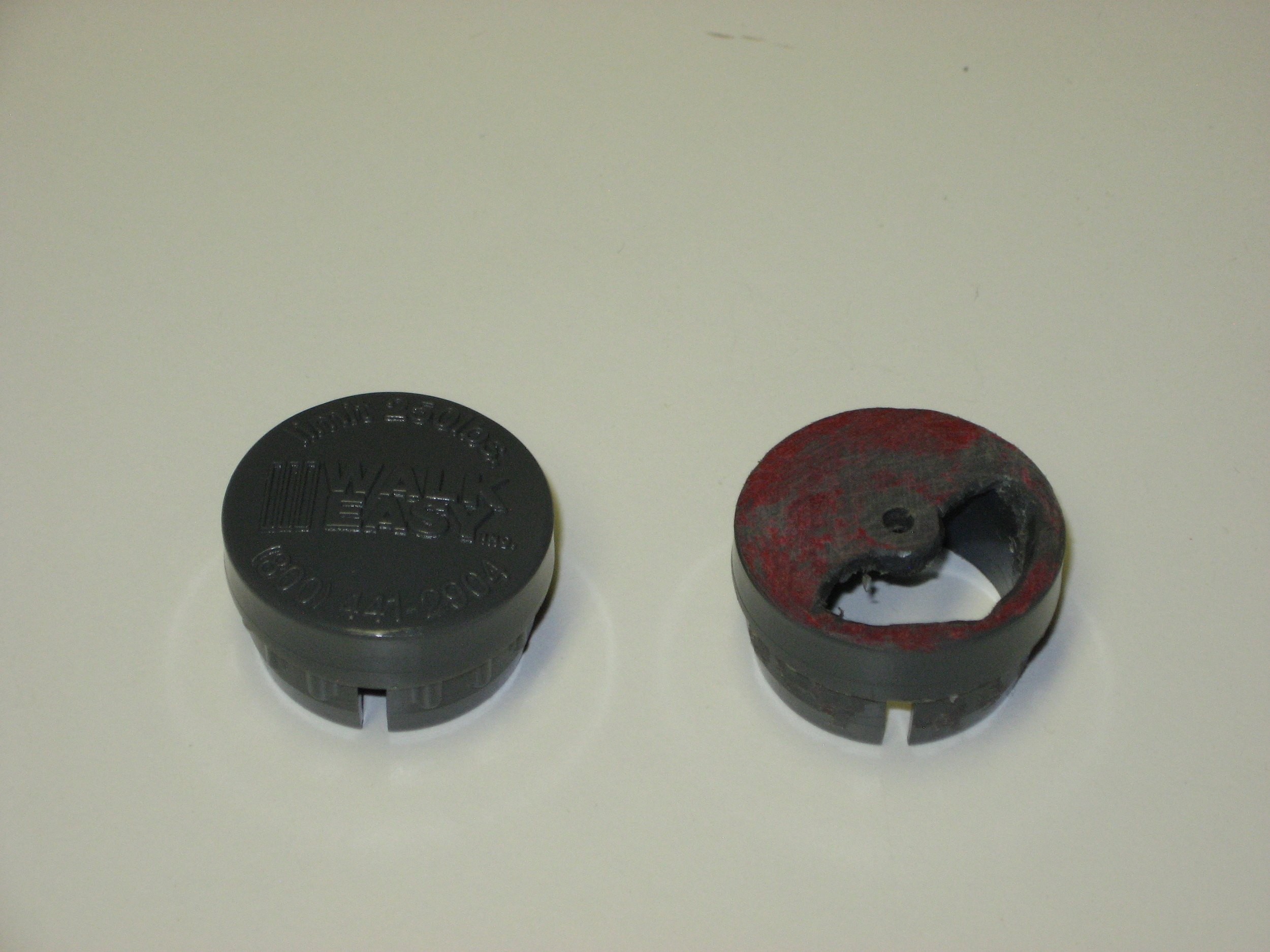
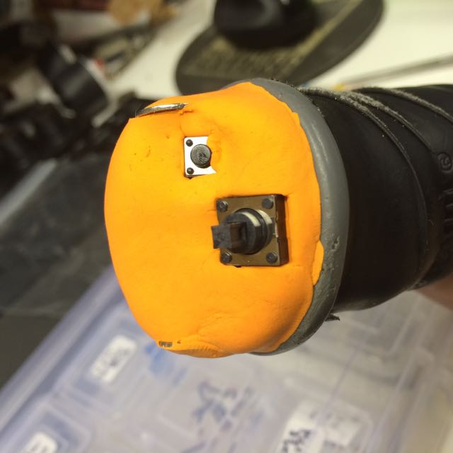
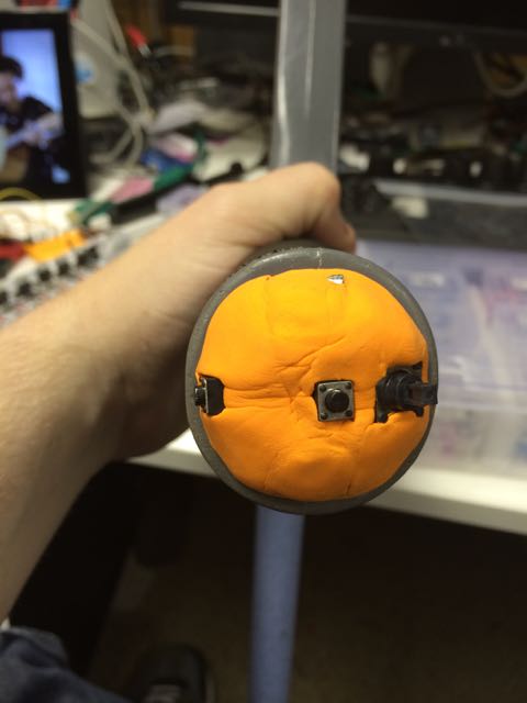
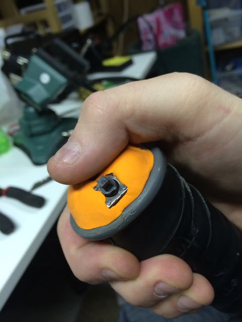
For the very first version, I used a the stock cap that comes with the crutches to cover the hole in the handle and modified it (read: cut and drilled it) to mount everything. It worked and it fit well, but it took almost 2 hours for each one I modified, and it as also really, really ugly when I was done with it.

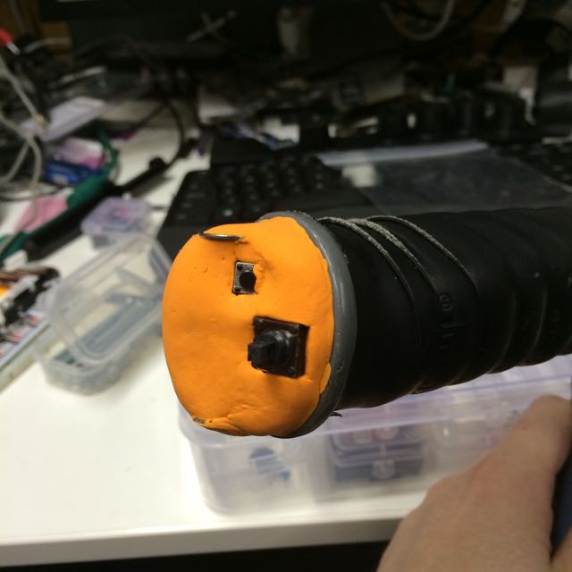
The replacement for this plug was the first thing I did when I got my 3D printer. It needed to be open enough to allow wires to go through but it also needed to let the controls be adjustable. Most important, though, it had to fit solidly in the handle as well as the original plug does.

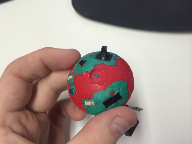
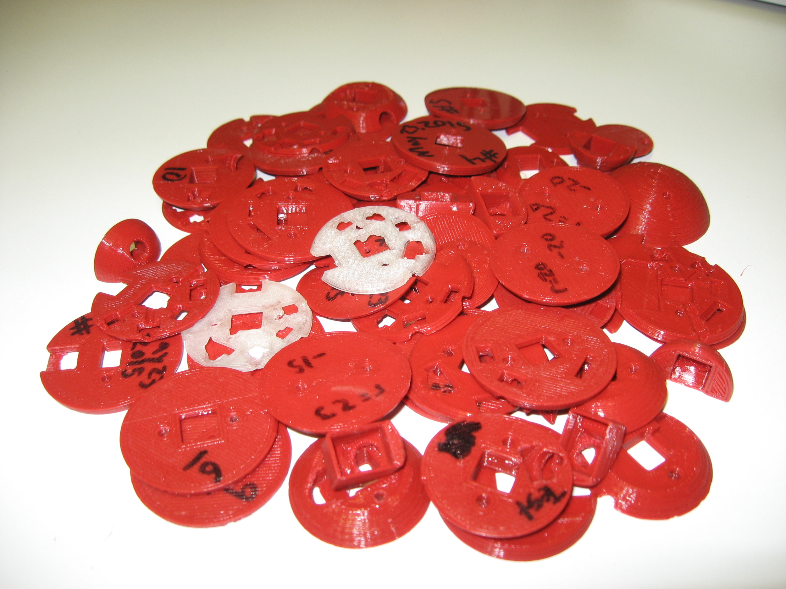
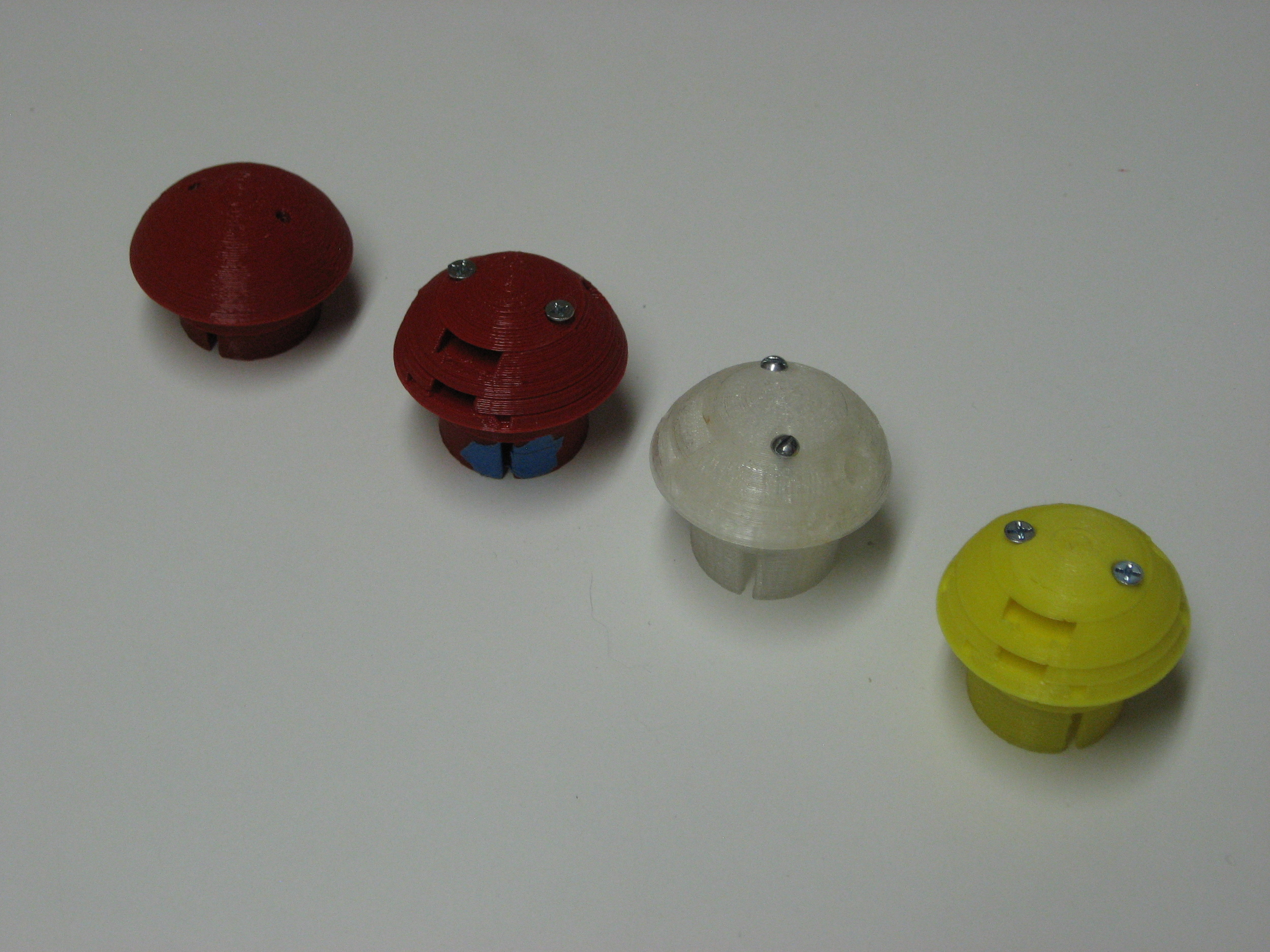
I went though a huge number of prototypes until I found a design that worked. And the prototypes in the photo are just the ones that worked, it doesn’t include all the ones that went directly in to the recycling bin.

When I first started building this part, I didn’t realize how important it was and how difficult it would be to build correctly. After all, if this piece doesn’t work properly, nothing else can do its job.

The current version is a big departure from the original hack, but it still does the job: hold things in place, be adjustable and still be strong.

Sapphire's Ancient History, Part 2: the stuff you can't see

Continuing from part one, which looked at the stuff on the outside of the crutch, this talks about the stuff on the inside: the actual electronics.

You’ll remember in the last post that the first hardware I used was the Adafruit Bluefruit EZ-Key, which is basically a very small Bluetooth keyboard. You can write up switches to it and it will send keyboard signals to the paired computer. It also has a built-in voltage regulator which made it really easy to get started with.

But I knew the Bluefruit would never work in production: it’s too expensive and you can’t reprogram it beyond changing the keystrokes it sends, so I needed to go deeper in to the Maker world.

I found a the Makey-Mate, a module from Sparkfun that is designed to make their “Makey-Makey” device completely wireles. It was prefect for my uses because it could be used on 3.3v or 5v and included battery-charging hardware and a battery connector!

Using the Arduino Micro I wrote code to communicate with the module, read buttons and send keystrokes. However, the Arduino Micro was not a long-term solution either since they are also to expensive to use in a production product. Using tutorials from the internet, I ported the code to the ATtiny84MCU and used that in concert with a priority encoder IC to get around the lack of pins.

This took the projected parts code from $60+ down to a much more reasonable $30. With a little bit of soldering it ended up fitting in the crutch handle quite nicely.  

The next version is going to swing back the other way. Although using the ATtiny84 is cost-effective, working with the limited memory and limited I/O has ended up being more trouble than it’s worth in the long run so the next prototypes will go back to using the ATmega328p. That means it won’t need a priority encoder, will have a lot more memory space and it will be compatible with the stock Arduino IDE right out of the box. And if the boards are designed and built smartly, the costs should be about the same.

(Next: Part 3: the stuff in the middle)

Sapphire's Ancient History, Part 1: the stuff you can see

Before Sapphire really existed, there was just the idea: can you make a Bluetooth remote-control fit inside the hands of a crutch? At the time I didn’t know a thing about micro-controllers, electronics or 3D printing but I still needed to create a proof of concept device.

Using a handful of off-the-shelf hardware, a soldering iron and some hand tools, the proof of concept was built in a month of weekends.

First breadboarded test.

First breadboarded test.

The main hardware is the Adafruit Bluefruit EZ-Key (black breadboard), which is basically a very small Bluetooth keyboard. When you send a signal to one if its 12 I/O lines, it sends a keystroke to whatever computer it is paired with. The buttons (green breadboard) give those signals. The Arduino Micro on the yellow breadboard is just there to act as a power supply.

Of course, having a whole Arduino Micro just to get power was pretty wasteful and it was eventually swapped with a bunch of AAA batteries. The project was finally, truly wireless.

Working from batteries.

Working from batteries.

After I proved it could work on batteries, I had to make a way to mount it to the crutch and have buttons. This was done by drilling holes in the existing handle “plug” that came with the crutch and using plastic that can be molded in hot water to hold the switches. Putting it all together you get something it pretty close to the Sapphire of today.

The first working prototype from July 2014.


Controls of first prototype close-up.

Controls of first prototype close-up.

Rocking the middle switch will change the track and pushing it in will toggle “play” or “pause”. The buttons to the left and right are volume control and the final button at the top is the “Home” button on iOS and Android. Even though the design wasn’t really ergonomic (and was pretty ugly), it proved that is could be built. This was July of 2014.

I then built over a dozen test controllers out of foam modeling clay; no wiring or electronics, just tests to find the right size and the best place for the switches.

Prototype made from modeling clay

Prototype made from modeling clay

After I found a design I thought would work, I needed to make it out of stronger stuff so I could wire it up and actually use it. I ended up using regular modeling clay formed into a semi-circle (using a light- bulb as the mold!) and then used a knife and a hobby drill to make the spaces for switches and wires. After baking the clay, soldering the components and mounting them, it was ready to be used for the first time.

This was a good way to test the fitting and get things wired but the clay was brittle and ended up cracking the first time I used it. To make a stronger version I made a mold using part of a soda can some casting material from a craft store.

I put the switchgear in to the mold, soldered it up and then poured liquid JB-Weld over it.

The result was a very tough, but very bad-smelling, copy. It also took a lot of time to wire up and cast, and the switches couldn’t be replaced without scrapping the whole unit so I knew this wouldn’t do for long.

I used this version for about 4 months until I bought a 3D printer and was able design a printable and repeatable assembly.

With a 3D printer, time to assemble the control hardware has gone from about 4 hours to under 1 hour. It can also be disassembled and parts inside can be replaced without having to snap the whole module.  

The production versions will probably move to injection-molded plastic, but with the advancements made in 3D printing it may make more sense to continue to use 3D printed hardware.

(Next: Part 2: the stuff you can’t see)